
What Is a Continuity Test?
A continuity test is an electrical check that determines whether a complete conductive path exists between two points. A meter applies a small test current and evaluates the resulting resistance. A low-resistance path generally indicates continuity, while a very high reading or open indication points to a break, loose connection, or disconnected component.
Quick Facts About Continuity Test
Category
Electrical diagnostic test
Used for
Finding open or interrupted paths
Common confusion
Continuity is not the same as voltage
Also called
Continuity Check
Often discussed with
Electrical Troubleshooting
Key Takeaways About Continuity Test
- The test checks for a complete conductive path.
- Power is normally removed before testing a circuit path.
- A continuity result does not confirm correct voltage.
How Continuity Test Works
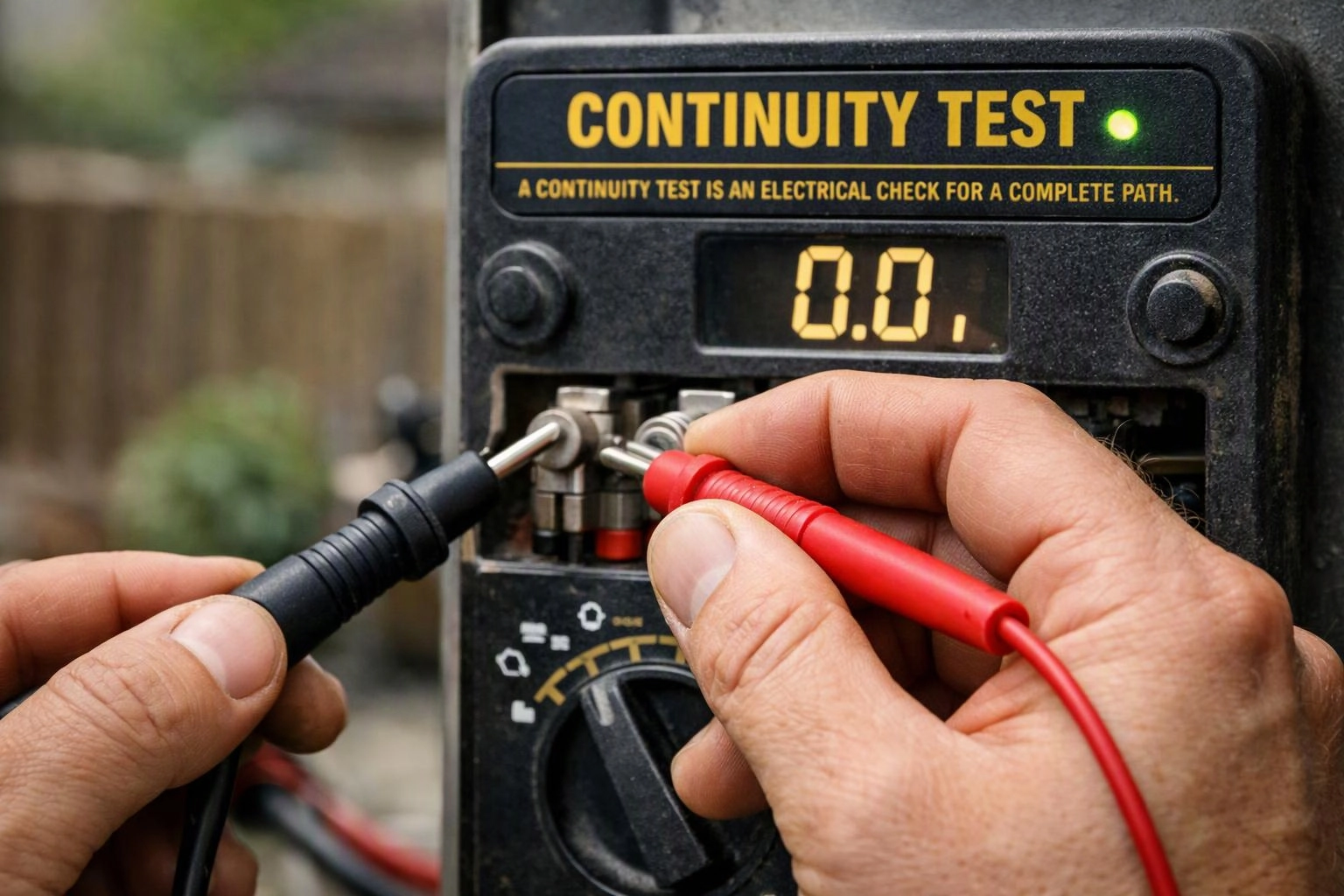
A continuity test sends a small electrical signal between two test points. The meter checks the resistance of the path and may show a low reading or sound an alert when the path is complete. An open indication means the signal cannot pass through the intended route.
Related glossary terms: Ohm, Voltage Tester, Wire Gauge.
Technicians use a multimeter to check wires, terminals, fuses, switches, and conductors. The circuit section being checked must be isolated from energized power so the meter can read the path accurately. A continuity result confirms that a connection exists, but it does not prove that the connection can carry its intended load. Resistance readings also help identify a weak connection that is present but not performing well.
From the San Bernardino Electrician team
When we troubleshoot a circuit, we identify the exact path that should connect, isolate that section, and test between suitable points. We compare the meter result with the circuit layout and inspect terminals when the reading changes during movement. This approach helps separate an open conductor from a control or component issue.
Continuity Test in Practice: A Real-World Example
A ceiling light stops working, and the switch appears intact. During electrical troubleshooting, we test continuity through the switch and the cable path with power isolated. An open result in the cable points to a broken connection or conductor that needs further inspection.
Related Services
Related Terms
Ohm
An ohm is the unit used to measure electrical resistance, which describes how strongly a material…
Voltage Tester
A voltage tester is a handheld electrical testing tool that detects whether voltage is present in…
Wire Gauge
Wire Gauge is a standardized way to describe a conductor’s thickness. The gauge identifies the wire’s…
Short Circuit
A Short Circuit is an unintended low-resistance path between electrical conductors that allows excessive current to…
San Bernardino Electrician
Have Questions About Continuity Test?
Contact San Bernardino Electrician for practical guidance on Continuity Test and related 24 hour electrician work in San Bernardino.