
What is Wiring Diagram?
Wiring Diagram is a visual plan that shows how electrical wires, devices, terminals, and power sources connect in a circuit or system. It uses lines, symbols, labels, and reference numbers to explain current paths and connection points. Electricians use wiring diagrams to install, test, troubleshoot, modify, and document electrical equipment safely.
Quick Facts About Wiring Diagram
Category
Electrical documentation
Used for
Installation, testing, troubleshooting, and repairs
Common confusion
A wiring diagram is not the same as a floor plan
Also called
Electrical wiring diagram, Connection diagram
Often discussed with
Lighting Installation, Circuit Breaker Repair
Key Takeaways About Wiring Diagram
- A wiring diagram shows connections, not just the physical location of electrical parts.
- Standard symbols identify switches, receptacles, breakers, motors, lights, and grounding paths.
- Labels and wire numbers help electricians trace circuits during installation and troubleshooting.
- A correct diagram must match the equipment, voltage, conductor count, and installation conditions.
- Never rely on a diagram alone to prove that a circuit is safe to touch.
Understanding Wiring Diagram
Wiring Diagramis a visual map of an electrical circuit. It shows the links.power source, conductors, switches, loads, and other devices. Unlike a picture of an installed system, the diagram focuses on electrical links. It shows the path that current should follow.
Related glossary terms: Branch Circuit, Electrical Panel, Junction Box.
Common diagrams use known electrical symbols for breakers, receptacles, lamps, motors, transformers, and grounding links. Lines show conductors. Labels identify wire numbers, terminal points, voltage levels, or cable types. A diagram may show one branch circuit, a control panel, a lighting system, or equipment.
How Wiring Diagram Works, Is Measured, or Is Used?
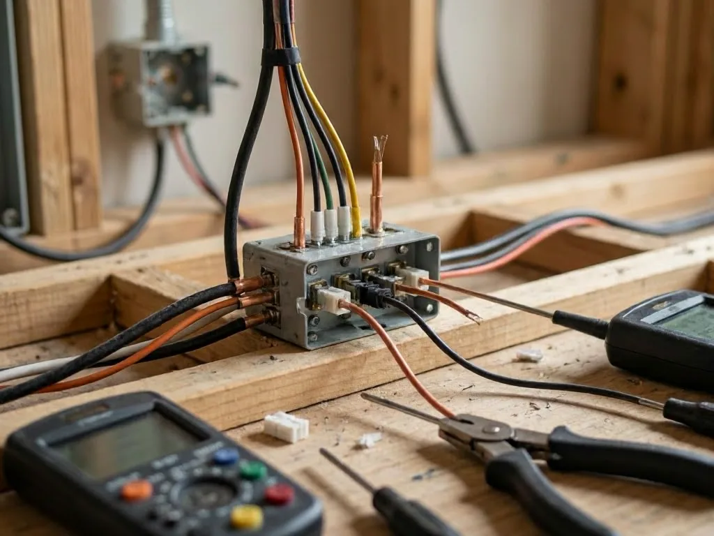
A wiring diagram doesn't have a physical measurement like voltage or resistance. Electricians read it as a connection plan. They compare each point on the page with its matching field terminal or part. The usual path starts at the source. It passes through safety devices and controls. It reaches the load and returns through the planned circuit path.
Reading starts with the legend, wire labels, and terminal marks. A technician can then trace the branch circuit from the circuit breaker to each device. They check conductor size, polarity, grounding, and control links. For fault finding, the technician compares the expected path with test results. They follow all needed safety steps first.
Several diagram styles serve different tasks. A schematic shows function with simple symbols. A connection diagram shows terminal-to-terminal wiring. A ladder diagram often shows control circuits in vertical logic paths. A one-line diagram sums up power flow with one line for several conductors.
Why Wiring Diagram Matters?
A wiring diagram reduces guesswork during electrical work. It helps identify the right terminal, wire, fuse, and control order. This happens before a part is moved or disconnected. That record can prevent reversed polarity, missing grounds, short circuits, and equipment damage. Some equipment needs a specific voltage or control signal.
Good records also improve future service. A technician can find a failed device faster when wire numbers match panel references. The diagram doesn't replace a code review or live testing. It gives those checks a clear starting point. It also records how the system should work.
When Wiring Diagram Matters Most?
Wiring Diagrambecomes useful during new installs, equipment replacement, remodeling, and urgent fault finding. It matters when several switches control one lighting load. It also matters when a motor uses a starter or relay. It helps when a circuit includes.ground-fault circuit interrupter or arc-fault circuit interrupter. Each device adds connection rules that may not show in the finished install.
The document also matters when an older system has changed many times. Unlabeled conductors, old cables, mixed colors, and missing splice records can make a drawing wrong. Before using an existing diagram, compare it with the equipment. Inspect accessible connections. Verify that power is off with a properly rated tester.
How Wiring Diagram Works, Is Measured, or Is Used?

A useful workflow starts by finding the system voltage, supply point, load rating, and disconnecting means. Next, trace each ungrounded conductor, grounded conductor, and equipment grounding path. Mark changes when field conditions differ. Keep the revised drawing with the panel or equipment records.
Technicians often pair a diagram with a multimeter, continuity tester, or circuit tracer. Test results should support the diagram, not replace it. For example, voltage at a line terminal doesn't prove a downstream load has a return path. A continuity result doesn't prove a circuit is safe or correctly powered.
Why Wiring Diagram Matters?
Good diagrams support safer choices about repairs and upgrades. They show if a proposed device fits the existing circuit. They show if a control needs a neutral conductor. They show if the install has the required grounding path. They also help separate a device failure from a supply problem. This can reduce needless part replacement.
Diagram quality depends on accuracy and clear details. A useful drawing lists the date, equipment, circuit name, wire sizes, safety devices, and clear revision notes. If a drawing conflicts with the National Electrical Code, maker instructions, or field conditions, review it before work starts.
When Wiring Diagram Matters Most?
Keep a current diagram after panel changes, room additions, generator work, lighting controls, and equipment replacements. It helps.junction box has several splices. It also helps when a transformer separates control voltage from line voltage. Clear records help future technicians avoid the wrong circuit. They also prevent wrong terminal connections.
For urgent service, a diagram can reduce the time needed to find a fault. This helps in a dark room, failed fan, or tripping circuit. In San Bernardino, CA, older homes and additions may have incomplete diagrams. Heat-related equipment changes may also cause problems. The safe response is to check the actual wiring first. Do this before restoring service or changing connections.
How to Evaluate Wiring Diagram?
- Check that the diagram identifies source voltage, breaker rating, conductor sizes, and equipment grounding connections.
- Compare every terminal label and wire number with the installed equipment before disconnecting conductors.
- Confirm that symbols and abbreviations match the diagram legend and manufacturer instructions.
- Look for revision dates, field changes, abandoned wires, and undocumented splices.
- Treat voltage, continuity, and polarity tests as separate checks rather than proof that the diagram is correct.
Related Concepts Compared
Wiring Diagram vs. Schematic
A schematic shows how a circuit functions with simplified symbols. A wiring diagram usually gives more detail about terminals, wire numbers, and physical connections.
Wiring Diagram vs. Electrical Floor Plan
An electrical floor plan shows where devices are located in a building. A wiring diagram explains how those devices connect electrically.
Wiring Diagram vs. One-line Diagram
A one-line diagram summarizes a power distribution system with simplified lines. A wiring diagram provides more detailed conductor and terminal information.
Expert Note
A field diagram may be technically neat yet still be wrong if later changes were never recorded. Verify terminal markings, conductor paths, and equipment ratings in the actual installation before treating an existing drawing as reliable.
Common Mistakes or Myths About Wiring Diagram
- Assuming wire color alone identifies a conductor or its function.
- Treating a floor plan as a complete wiring diagram.
- Ignoring later alterations, abandoned wires, or undocumented junctions.
- Testing a live circuit without following proper electrical safety procedures.
- Replacing a device without recording terminal connections and wire labels.
Wiring Diagram in Practice: A Real-World Example
A kitchen lighting diagram may show a breaker feeding a switch, the switch sending power to a light fixture, and the fixture returning through a neutral conductor. If the light stays on when the switch is off, the diagram and field wiring can be compared to find a misconnection.
Sources & Further Reading on Wiring Diagram
- National Fire Protection Association, National Electrical Code
- Occupational Safety and Health Administration, Electrical Safety
- Electrical Safety Foundation International, Electrical Safety
Related Services
Related Terms
Branch Circuit
Branch Circuit is the portion of an electrical system that carries power from the final overcurrent…
Electrical Panel
Electrical Panel is the main enclosure that receives electricity from a utility service and distributes it…
Junction Box
Junction Box is an enclosed electrical container that protects wire connections where two or more cables…
National Electrical Code
National Electrical Code is a safety standard published by the National Fire Protection Association that sets…
SanBernardino-Electrician.com
Have Questions About Wiring Diagram?
Contact SanBernardino-Electrician.com for practical guidance on Wiring Diagram and related 24 hour electrician work in San Bernardino.